Repair: Difference between revisions
Jump to navigation
Jump to search
No edit summary |
No edit summary |
||
| (9 intermediate revisions by the same user not shown) | |||
| Line 1: | Line 1: | ||
I printed the schematics, figured out how to remove the Relay Shelf, and began: |
I printed the schematics, figured out how to remove the Relay Shelf, and began: |
||
[[File:30s1_relayshelf_halfout_selfie.jpg|500px|thumb|center |
[[File:30s1_relayshelf_halfout_selfie.jpg|500px|thumb|center|Relay Shelf half-out, |
||
probably far enough to work on]] |
|||
* Bias Transformer T203 was utterly toasted... burned and bubbled. Fortunately Peter Dahl / Hammond offer a top-quality replacement - Whew! Nearby components and the wiring-harness appeared miraculously undamaged! |
* Bias Transformer T203 was utterly toasted... burned and bubbled. Fortunately Peter Dahl / Hammond offer a top-quality replacement - Whew! Nearby components and the wiring-harness appeared miraculously undamaged! |
||
* Bias rectifiers had been changed to silicon diodes, mounted on a terminal-strip. However, the terminal-strip was bent over, shorting at least one (perhaps two) leads to the chassis. |
* Bias rectifiers had been changed to silicon diodes, mounted on a terminal-strip. However, the terminal-strip was bent over, shorting at least one (perhaps two) leads to the chassis. |
||
| Line 21: | Line 22: | ||
Here's a visual summary: |
Here's a visual summary: |
||
[[File:Burned_bias_transformer_t203.jpg|500px|thumb|center|Burned and bubbled T203 Bias Transformer. Bent-over and shorted Bias diodes CR207 & CR208, along with step-start diode CR205]] |
|||
[[File:bent_bruised_shorted_r218.jpg|500px|thumb|center|Bent, bruised and shorted R218 (bias switching between CW and SSB)]] |
|||
[[File:30s1_hacked_C211.jpg|500px|thumb|center|Questionable C211 (12VDC filtering)]] |
|||
[[File:30s1_decrepit_T202.jpg|500px|thumb|center|Filament transfomer T202 had broken leads!]] |
|||
[[Dealing with the Overheated and Cracked R232]] |
|||
[[Dealing with the RF Output]] |
|||
[[BIAS Transformer T203, and Associated Circuitry]] |
|||
[[Screen Supply Overhaul]] |
|||
[[12V Safety and Control]] |
|||
[[CR216 and BIAS Multi-Metering]] |
|||
[[Primary AC Wiring]] |
|||
[[Dials]] |
|||
[[Power Supply & Lower Compartment]] |
|||
[[Tuning & Loading Meter Circuit]] |
|||
Latest revision as of 17:56, 12 August 2020
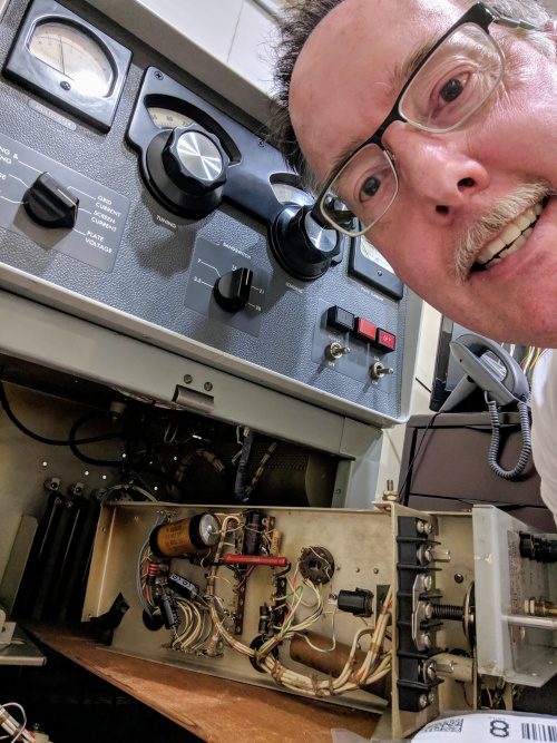
I printed the schematics, figured out how to remove the Relay Shelf, and began:
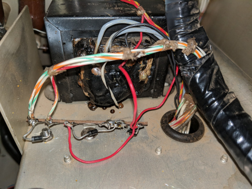
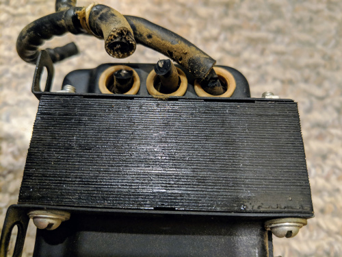
- Bias Transformer T203 was utterly toasted... burned and bubbled. Fortunately Peter Dahl / Hammond offer a top-quality replacement - Whew! Nearby components and the wiring-harness appeared miraculously undamaged!
- Bias rectifiers had been changed to silicon diodes, mounted on a terminal-strip. However, the terminal-strip was bent over, shorting at least one (perhaps two) leads to the chassis.
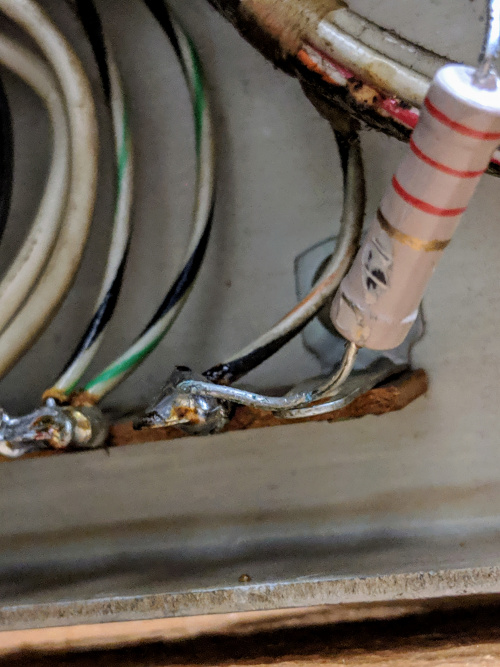
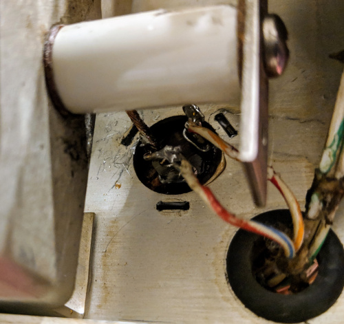
- In a similar vein on the underside of the Relay Shelf, Bias divider resistor R218 was bent to touch the chassis
- Next to this bent/touching resistor, I then saw the cracked-and-broken 10-ohm R232 (limits screen-supply inrush current).
- And, the RF output connector had been changed from the N-flanged original, to a loose-and-sloppy SO-239 barrel (featuring mangled threads which prevented tightening).
- Time-delay thermal relay K202 was only 35-seconds, not 3-minutes as Collins designed (to ensure V101's cathode is properly heated before use).
- Rectifier-filament transformer T202 had cracked-and-broken secondary leads. Because this amplifier had replacment solid-state HV rectifiers, I decided to simply remove the no-longer-needed T202.
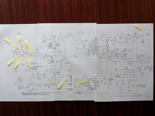
Here is a photo of the taped-up schematic, with my annotations and some flags showing the components I decided to replace:
Beyond these quickly-visible electrical problems, I noted that there were some other changes and physical areas needing my attention too:
- The 3B28 rectifiers have been changed to solid-state modules. These modules were mounted to a thin piece of plywood, and look electrically OK... but it is not a thing of beauty
- The 12AL5 dual-diode ALC rectifier-tube has also been changed to a plug-in solid-state diode. This looked tidy. It functionally implements Collins' Service Bulletin SB-3, Nov 1/69 (space-charge standoff voltage from 12AL5 tube)
- The "TUNING" dial had some rubbed/dissolved printing 'way down at the low-end of the dial. The dial functioned, but I knew this would truly annoy me.
- The "LOADING" dial had cracked and been repaired, with a visible glue-line. The repair was very neatly done, but I would find it a constant aggravation simply knowing it was there.
- The 12V filter-capacitors C211A and C211B (a two-section can) looked sketchy: A previous repair fished up into the internals of the can to effect a connection to one of the caps (!), and a scary bare wire snaked through (grounded/conductive) obstacles from the cap to the circuit. It's possible all this did work, but I'd lose sleep if I ignored this area...
Here's a visual summary:
Dealing with the Overheated and Cracked R232
BIAS Transformer T203, and Associated Circuitry
