Updates and Changes
Raising CW Plate- and Screen-Voltages
Collins' reduction in High Voltage and Screen Voltage when using CW mode held back the 4CX1500B gain, and total-power. I was almost at the point of using the SSB setting for CW (as many do), when Chet VE3CFK pointed out...
That feeding both the primary wires from the front-panel-switch to the SSB connections on the transformer would give me a constant 3kV plate-voltage, and the elevated screen-voltage, no matter the mode. In fact, doing this means the only difference between SSB and CW is the negative grid-bias, and the resulting Class of operation.
The realization of Chet's suggestion: simply moving the CW-primary-power wire from Term #1 to Term #2, and similarly moving Term #6 to Term #5:

Now I have good gain and total power! Thanks, Chet! Here's a view of comfortable operating conditions now, for CW:

Raising the Screen supply meant my C204 Voltage rating was marginal... Here, I did a mod to a mod ;-) 500V / 105C rating are improvments over the 450V/85C new capacitor I recently installed.

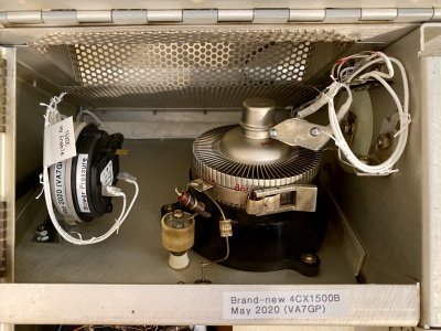
Installing the 4CX1500B


Date-code of (mid-December) 1984. 12 hours of filament-only to getter the tube, after such long storage.

This photo shows 1kW into my dummy-load, making it sweat a bit :-)
But my calculation of the DC input power, now compared with the RF output-power, leads me to question my Plate Current meter accuracy. Another detour...
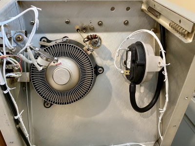
Thermal Overload Switch K102
My thermal sensor kicked my amp offline a couple of times, at only modest power-levels. Perhaps decades of time have taken their toll on the sensor; perhaps tube-changes have un-calibrated it; certainly my blower-motor-change will have altered it's response. The purpose of the thermal sensor: to open the HV-enable 12V circuit and K203 (primary AC power) if the tube gets too hot. The tube can get too hot with either excess dissipation, or lack of cooling-airflow.
I changed this protection to accurately focus on protecting the tube against overtemperature and also against loss of cooling airflow.
- Thermal and Pressure switches to replace Collins Overtemp K102
-
 Rear View of the RF Compartment, Showing New Thermal-Safety
 -
 Top View of the RF Compartment, Again Showing Thermal-Safety


-
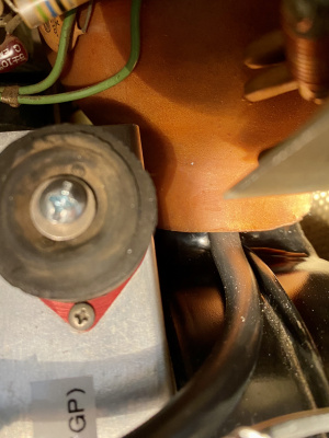 Air-Pressure sensing tube simply stuck up between blower nozzle, and flexible coupling-boot

Dial Lights "ON" when Amp is Ready
I re-wired the dial-lights so they will illuminate only after the warm-up delay has passed and K202 closes. Not only does this indicate visually that the amp has completed the 3min warm-up and ready to hit the "ON" push-button, but it also confirms 12V is available to energize K203 - maybe this will help troubleshooting one day. (Technical note: this "delay completed" lighting moves the dial bulbs from 12VAC to ~15VDC operation).
Final touch for the dial-light mod: hand-lacing!
