Updates and Changes
Boosting Screen Voltage
I bought a 100VA 120V transformer, with the intention of boosting the screen voltage. This Triad FD8-120 features a pair of primary windings - I connected these windings in series for 240VAC operation, and wired them to T201 SSB terminals, with the result:
- When the user alters the AC input-jumper, this boost will follow and operate from either 240VAC (as now), or 120VAC, just like T201
- This connection should give 100V screen-supply boost in SSB, and a lower 65V boost in CW, IF I HAD NOT ALTERED THE SSB/CW 240VAC PRIMARY CONNECTIONS. But in my particular case, the Screen Boost will always be the SSB value. The boost will only come alive once the front-panel ON HV button is pressed. Repeating the same (no-load) measurements as above:
- Measuring Screen Boost Voltages
-
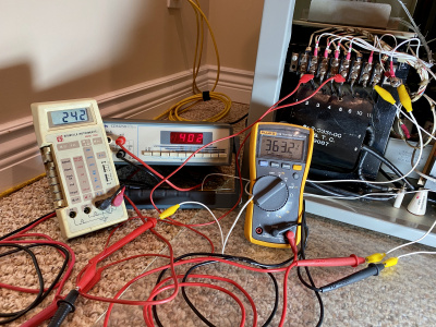 SSB Screen Boost - about 100VDC
 -
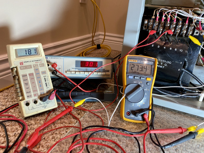 CW Screen Boost - about 40VDC
 - 0.980 amps without resistor nor any nozzle-restriction (121VAC)
- 0.76 amps with resistor in steady-state (10-12s after start)
- 93VAC across motor, with resistor, in steady-state
- Measuring blower-rotational-speed
-
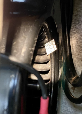 Reflective Tape Applied to Blower-Squirrel-Cage Perimeter
 -
 30S-1 Blower Speed (rpm) Measurement
 - Thermal and Pressure switches to replace Collins Overtemp K102
-
 Rear View of the RF Compartment, Showing New Thermal-Safety
 -
 Top View of the RF Compartment, Again Showing Thermal-Safety
 -
 Air-Pressure sensing tube simply stuck up between blower nozzle, and flexible coupling-boot


Again, three meters show the boost for SSB, and CW. The CW Screen Voltage reading appears lower-than-expected, because these measurements are made prior to raising the Plate + Screen voltage; thus, the CW primary-winding voltage is only about 2/3 that obtained in SSB mode.

The connections to the barrier-strip are clearly labelled; the wires are neatly laced - pretty much the way Collins might have done it :-)
Raising CW Plate- and Screen-Voltages
Collins' reduction in High Voltage and Screen Voltage when using CW mode held back the 4CX1500B gain, and total-power. I was almost at the point of using the SSB setting for CW (as many do), when Chet VE3CFK pointed out...
That feeding both the primary wires from the front-panel-switch to the SSB connections on the transformer would give me a constant 3kV plate-voltage, and the elevated screen-voltage, no matter the mode. In fact, doing this means the only difference between SSB and CW is the negative grid-bias, and the resulting Class of operation.
The realization of Chet's suggestion: simply moving the CW-primary-power wire from Term #1 to Term #2, and similarly moving Term #6 to Term #5:

Now I have good gain and total power! Thanks, Chet! Here's a view of comfortable operating conditions now, for CW:

Raising the Screen supply meant my C204 Voltage rating was marginal... Here, I did a mod to a mod ;-) 500V / 105C rating are improvments over the 450V/85C new capacitor I recently installed.

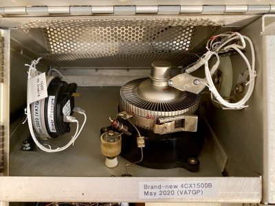
Installing the 4CX1500B


Date-code of (mid-December) 1984. 12 hours of filament-only to getter the tube, after such long storage.

This photo shows 1kW into my dummy-load, making it sweat a bit :-)
But my calculation of the DC input power, now compared with the RF output-power, leads me to question my Plate Current meter accuracy. Another detour...
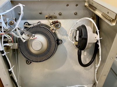
Cooling
Collins' original blower is very quiet. Nicely quiet. This is pretty much a result of laminar-airflow over the tube-fins, with a (nominal) 1800rpm motor.
The fin-design of the 4CX1500B includes offset-punched sections of each fin, intentionally to cause turbulence and remove more heat. I made that much worse :-) by swapping blower-motors - I swapped in the popular 3000rpm Dayton 4M093E. Some correspondance and digging through Collins' maillist archives led me to choose a 50-ohm series-resistor, primarily to keep the motor from overheat-tripping (this motor will overheat without some sort of slow-down, because it's intended to have airflow over the motor, and in this 30S-1 application it does not have cooling airflow over it).

The line-up of prime-suspects for the blower-motor change :-)

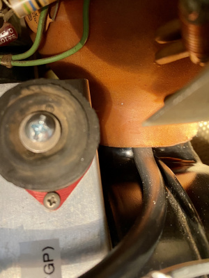
Motor changed, resistor mounted to housing, blower re-assembled. Home at long last :-) The lower mounting bolt took me 4hrs just to get it installed. I later read Mr. Carn's article in "The Signal" which says it should be a stud - they say the best advice comes just after the job is completed :-O The only one good thing about my (re-)using a bolt: it was easy to adjust the front mount, so that the weight of the motor is hanging equally from the top-mounts - just look at the "angle of the dangle" for this bolt, in the power-supply compartment. It's neutral and balanced when the bottom bolt hangs perfectly vertical. The 50-ohm power resistor is screw-mounted on the lip of the blower intake, where it will receive some cooling, but not noticeably obstruct airflow.
My cut-off tool got a workout: the Dayton motor has front and rear mounting-bolts; I didn't like the knuckle-slicing appearance of the rear ones so I cut them off and added some protective heatshrink. I trimmed the front bolts down, to allow more lattitude in adjusting the squirrel-cage. And my 1/4" nut-driver was too long to fit into the blower compartment, so I cut that too :-)
For this 50-ohm resistor, I measured:
Pretty much, this shifts the original motor-dissipation from 120W without a resistor, down to 70W in the motor and 32W in the resistor. Subjectively, the airflow seems the same, but the motor-temperature will be 'way down.
Test driving the new blower made my beach-towel wave in the wind, from 3 feet away :-) Too much is just about right :-)

An idea of how this sytem will work, when the forces of Hot and Cold do battle! Looks like the forces of Cold will win! This graph was generated with 1500W dissipated in the 4CX1500B plus 20% margin... I won't operate at this point, so I'll have even more margin when I operate at more-modest levels. To push the tube up against the cooling-limits would require something like 3kW DC input!!! Even bleary-eyed, at the end of a long contest, starved for food and water, I am incapable of damaging my 30S-1 :-)
Predicted performance was reassuring, but I felt the need to measure and determine actual performance.
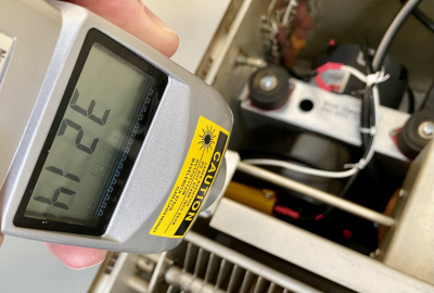
Tachometer: 3214rpm
Anode Temperature (750W CW Output):
Manometer Pressure:


And Then...
I bought a Variable-Voltage / Variable Frequency controller! This V/F motor drive is ~perfect~ for the Dayton shaded-pole motor... My Plan: slow the motor when possible and enjoy quiet-ness, then speed it up when cooling is required. This V/F drive can be controlled with a 0-5V signal, so ... :-)
Thermal Overload Switch K102
My thermal sensor kicked my amp offline a couple of times, at only modest power-levels. Perhaps decades of time have taken their toll on the sensor; perhaps tube-changes have un-calibrated it; certainly my blower-motor-change will have altered it's response. The purpose of the thermal sensor: to open the HV-enable 12V circuit and K203 (primary AC power) if the tube gets too hot. The tube can get too hot with either excess dissipation, or lack of cooling-airflow.
I changed this protection to accurately focus on protecting the tube against overtemperature and also against loss of cooling airflow.


Dial Lights "ON" when Amp is Ready
I re-wired the dial-lights so they will illuminate only after the warm-up delay has passed and K202 closes. Not only does this indicate visually that the amp has completed the 3min warm-up and ready to hit the "ON" push-button, but it also confirms 12V is available to energize K203 - maybe this will help troubleshooting one day. (Technical note: this "delay completed" lighting moves the dial bulbs from 12VAC to ~15VDC operation).
I sourced this "ready-to-go" supply from the panel-mounted S208 "OFF" pushbutton. The outermost terminal loses it's 15VDC momentarily when S208 is pushed, so I used the innermost terminal (next to the red "ON" light) which remains live always (well, after 3min warm-up).
Final touch for the dial-light mod: hand-lacing!

LEDs
So, when I mentioned above that the dial-bulbs are now operating from ~15VDC ... I replaced the dial-bulbs with some ubiquitous "pinball" bulbs, meant to replace #44 and #47 incandescent bulbs. My particular LED bulbs have a diode-bridge in the base and are DC-polarity insensitive. However, they were designed to operate on 6.3VAC, not my ~8VDC :-O At first, they were great and very bright. After a while, they began to "stutter" - not really "flicker" and certainly in no relation to any supply-ripple, but a slower, cyclical blink-stutter, sometimes opposite to each other. Hmmm...
I dug in: checked all connections, cleaned the bulb-socket contacts, bypassed all safety and thermal-timer connections and otherwise made sure the 30S-1 itself didn't generate the flicker at any point in the 12VAC circuitry. Then, I got out the oscilloscope, to check things: the mid-voltage between the LEDs was erratic and crazy. From this, I conjectured the LED bulbs were failing internally, possibly due to overheating. Replacing both the high- and low-side bulbs brought immediate relief and proper operation, but I knew it would not last ...
So - from my always-HOT side of S208 (which supplies the dial-LED bulbs) I added a 5.1V zener diode, effectively knocking the voltage down something like 5.5V actual. This results in the pair of LEDs receiving ~10V total, or ~5V across each. This reduction from 6.3VAc to 5VDC resulted in a less-bright and more-yellowish light... which I find AWESOME!! And I hope they'll last a very long time.
NOTE: LEDs are "fast", and the DC I now use for the dial-bulbs isn't well-filtered. There is a subtle 120Hz flicker when I TX and the relays load this lightly-filtered DC supply. Again, the slight dimming and slight flicker in TX seems a beautiful symbolism for my 30S-1 "picking up and shouldering the load". Appropriate for the era!