Plan Execution
Work began on February 10, 2020.

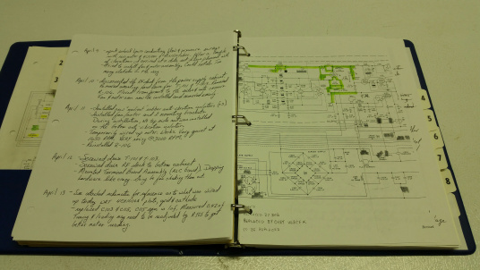
A working diary was maintained throughout the rebuild. This serves as a visual and written confirmation that something was done as opposed to using ones memory. Additionally it is a convenient place to store photos, schematics and other notes pertaining to the build. Most importantly it is a place to create "Things to remember to do". Such as "retightening ALL HV connections before turning power on". There were times during the rebuild where it was necessary to disconnect something in the HV circuit. I didn't want to forget to reconnect and tighten, so a deliberate note was made on the "Things to re..." page.
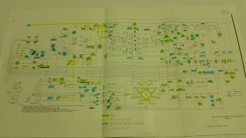
Another invaluable "checklist" item was a copy of the complete schematic.

Each component of the amplifier was checked for conformance with the Collins specification, and if found to be out of tolerance, was replaced. I used a tighter tolerance than Collins specified. For example if the specification for a resistor was 10%, I made sure it was 5% or better. Each component on the schematic was color coded. GREEN for checked and OK as is, YELLOW denoted that Bob have replaced the component and was validated as OK and BLUE denoted that it was replaced by myself because it was out of specification, looked compromised or just wasn't shiny enough.
All told there were 58 components replaced by myself and 8 replaced by Bob. Bob had actually replaced more than 8 components. Some electrolytics he had replaced were possibly 18 years old. Although they may have never seen voltage, I automatically assumed that they needed replacement. It's my philosophy towards electrolytics. If they are older than 10 years old. Replace them. The cheap no-name electrolytics you find on eBay come from less than reputable sources and are not of the quality of Vishay or Phillips. So if in doubt, replace.
Some of the major components replaced were relays, step-start resistors, bleeder resisters, filament adjust potentiometer, the SSB/CW switch and the 4CX1000A. Fortunately all the transformers and chokes were okay as received. I could not tell whether they were originals, replacements, or originals that were repainted. In the final analysis it really did not matter. They all worked.
One item that was extensively reconditioned was the cooling system. The motor and fan were filthy. They were completely cleaned and degreassed. I went further and replaced the stock motor with a 3000 RPM motor replacing the stock 1500 RPM motor. Also installed was an electronic variable speed controller with override switch. See photo below. These were mounted in an inconspicuous spot that would only be noticeable if you got down on your hands and knees but also located so that the operator could quickly open the main cabinet door, flip a switch and achieve the desire flow condition. Plus it was mounted in such a manor than the Collins aficionado would have to really go out of his way to find the two holes that were put in the chassis.
Each sub-system was individually validated. For example. The 180 second cathode warm-up interlock circuit was validated by disconnecting the +12 VDC source with a fused +12VDC power supply and powered up. If the circuit did not energize the required relay, well, there was more trouble shooting to do. The HV supply, the bias supply, the screen voltage supply, the antenna changeover circuitry, the metering circuitry, etc were all independently validated. This made trouble shooting the integrated system easier knowing where the fault was NOT located.