Updates and Changes: Difference between revisions
| Line 53: | Line 53: | ||
<span> |
<span> |
||
[[File:Preparing_blower_motor_change.jpg|500px|thumb|left]] |
[[File:Preparing_blower_motor_change.jpg|500px|thumb|left]] |
||
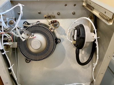
The line-up of prime-suspects for the blower-motor change :-) |
The line-up of prime-suspects for the blower-motor change :-) |
||
</span> |
</span> |
||
</p> |
</p> |
||
<br clear=all> |
<br clear=all> |
||
<<photo of installed parts to come>> |
|||
<p> |
|||
<span> |
|||
[[File:Dayton_motor_installed.jpg|500px|thumb|right]] |
|||
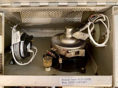
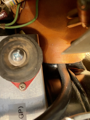
Motor changed, resistor mounted to housing, blower re-assembled. Home at long last :-) The lower mounting bolt took me 4hrs just to get it installed. I later read Mr. Carn's article in "The Signal" which says it should be a stud - they say the best advice comes just after the job is completed :-O The only one good thing about my (re-)using a bolt: it was easy to adjust the front mount, so that the weight of the motor is hanging equally from the top-mounts - just look at the "angle of the dangle" for this bolt, in the power-supply compartment. It's neutral and balanced when the bottom bolt hangs perfectly vertical. |
|||
The 50-ohm power resistor is screw-mounted on the lip of the blower intake, where it will receive some cooling, but not noticeably obstruct airflow. |
|||
</span> |
|||
</p> |
|||
<br clear=all> |
|||
My cut-off tool got a workout: the Dayton motor has front and rear mounting-bolts; I didn't like the knuckle-slicing appearance of the rear ones so I cut them off and added some protective heatshrink. I trimmed the front bolts down, to allow more lattitude in adjusting the squirrel-cage. And my 1/4" nut-driver was too long to fit into the blower compartment, so I cut that too :-) |
My cut-off tool got a workout: the Dayton motor has front and rear mounting-bolts; I didn't like the knuckle-slicing appearance of the rear ones so I cut them off and added some protective heatshrink. I trimmed the front bolts down, to allow more lattitude in adjusting the squirrel-cage. And my 1/4" nut-driver was too long to fit into the blower compartment, so I cut that too :-) |
||
Revision as of 21:07, 29 June 2021
Raising CW Plate- and Screen-Voltages
Collins' reduction in High Voltage and Screen Voltage when using CW mode held back the 4CX1500B gain, and total-power. I was almost at the point of using the SSB setting for CW (as many do), when Chet VE3CFK pointed out...
That feeding both the primary wires from the front-panel-switch to the SSB connections on the transformer would give me a constant 3kV plate-voltage, and the elevated screen-voltage, no matter the mode. In fact, doing this means the only difference between SSB and CW is the negative grid-bias, and the resulting Class of operation.
The realization of Chet's suggestion: simply moving the CW-primary-power wire from Term #1 to Term #2, and similarly moving Term #6 to Term #5:

Now I have good gain and total power! Thanks, Chet! Here's a view of comfortable operating conditions now, for CW:

Raising the Screen supply meant my C204 Voltage rating was marginal... Here, I did a mod to a mod ;-) 500V / 105C rating are improvments over the 450V/85C new capacitor I recently installed.

Installing the 4CX1500B


Date-code of (mid-December) 1984. 12 hours of filament-only to getter the tube, after such long storage.

This photo shows 1kW into my dummy-load, making it sweat a bit :-)
But my calculation of the DC input power, now compared with the RF output-power, leads me to question my Plate Current meter accuracy. Another detour...
Cooling
Collins' original blower is very quiet. Nicely quiet. This is pretty much a result of laminar-airflow over the tube-fins, with a (nominal) 1800rpm motor.
The fin-design of the 4CX1500B includes offset-punched sections of each fin, intentionally to cause turbulence and remove more heat. I made that much worse :-) by swapping blower-motors - I swapped in the popular 3600rpm Dayton 4M093E. Some correspondance and digging through Collins' maillist archives led me to choose a 50-ohm series-resistor, primarily to keep the motor from overheat-tripping (this motor will overheat without some sort of slow-down, because it's intended to have airflow over the motor, and in this 30S-1 application it does not have cooling airflow over it).

The line-up of prime-suspects for the blower-motor change :-)

Motor changed, resistor mounted to housing, blower re-assembled. Home at long last :-) The lower mounting bolt took me 4hrs just to get it installed. I later read Mr. Carn's article in "The Signal" which says it should be a stud - they say the best advice comes just after the job is completed :-O The only one good thing about my (re-)using a bolt: it was easy to adjust the front mount, so that the weight of the motor is hanging equally from the top-mounts - just look at the "angle of the dangle" for this bolt, in the power-supply compartment. It's neutral and balanced when the bottom bolt hangs perfectly vertical. The 50-ohm power resistor is screw-mounted on the lip of the blower intake, where it will receive some cooling, but not noticeably obstruct airflow.
My cut-off tool got a workout: the Dayton motor has front and rear mounting-bolts; I didn't like the knuckle-slicing appearance of the rear ones so I cut them off and added some protective heatshrink. I trimmed the front bolts down, to allow more lattitude in adjusting the squirrel-cage. And my 1/4" nut-driver was too long to fit into the blower compartment, so I cut that too :-)
For this 50-ohm resistor, I measured:
- 0.980 amps without resistor nor any nozzle-restriction (121VAC)
- 0.76 amps with resistor in steady-state (10-12s after start)
- 93VAC across motor, with resistor, in steady-state
Pretty much, this shifts the original motor-dissipation from 120W without a resistor, down to 70W in the motor and 32W in the resistor. Subjectively, the airflow seems the same, but the motor-temperature will be 'way down.
Test driving the new blower made my beach-towel wave in the wind, from 3 feet away :-) Too much is just about right :-)
<<graph of predicted blower performance>>
Predicted performance was reassuring, but I felt the need to measure and determine actual performance. Tachometer: 3214rpm Temperature: Manometer Pressure:
And Then...
I bought a Variable-Voltage / Variable Frequency controller! This V/F motor drive is ~perfect~ for the Dayton shaded-pole motor... My Plan: slow the motor when possible and enjoy quiet-ness, then speed it up when cooling is required. This V/F drive can be controlled with a 0-5V signal, so ... :-)
Thermal Overload Switch K102
My thermal sensor kicked my amp offline a couple of times, at only modest power-levels. Perhaps decades of time have taken their toll on the sensor; perhaps tube-changes have un-calibrated it; certainly my blower-motor-change will have altered it's response. The purpose of the thermal sensor: to open the HV-enable 12V circuit and K203 (primary AC power) if the tube gets too hot. The tube can get too hot with either excess dissipation, or lack of cooling-airflow.
I changed this protection to accurately focus on protecting the tube against overtemperature and also against loss of cooling airflow.
- Thermal and Pressure switches to replace Collins Overtemp K102
-
 Rear View of the RF Compartment, Showing New Thermal-Safety
 -
 Top View of the RF Compartment, Again Showing Thermal-Safety


-
 Air-Pressure sensing tube simply stuck up between blower nozzle, and flexible coupling-boot

Dial Lights "ON" when Amp is Ready
I re-wired the dial-lights so they will illuminate only after the warm-up delay has passed and K202 closes. Not only does this indicate visually that the amp has completed the 3min warm-up and ready to hit the "ON" push-button, but it also confirms 12V is available to energize K203 - maybe this will help troubleshooting one day. (Technical note: this "delay completed" lighting moves the dial bulbs from 12VAC to ~15VDC operation).
Final touch for the dial-light mod: hand-lacing!
