BIAS Transformer T203, and Associated Circuitry: Difference between revisions
No edit summary |
No edit summary |
||
| Line 38: | Line 38: | ||
<p> |
<p> |
||
<span> |
<span> |
||
[[File:C209_c210.jpg|500px|thumb| |
[[File:C209_c210.jpg|500px|thumb|right]] |
||
C209 and C210 upgraded, mechanically secured, and labelled |
C209 and C210 upgraded, mechanically secured, and labelled |
||
A pair of new capacitors - same 50uF, but uprated from 150VDC to 250VDC, working temperature range -20C to +85C. The capacitors are labelled, as is the T203 Bias-Transformer centre-tap connection (I may be the next person helped by this clear labelling!). An additional layer of clear heat-shrink was added to ensure HV sturdiness, and the nylon mounting clamps are spaced a further 8mm off the chassis. |
A pair of new capacitors - same 50uF, but uprated from 150VDC to 250VDC, working temperature range -20C to +85C. The capacitors are labelled, as is the T203 Bias-Transformer centre-tap connection (I may be the next person helped by this clear labelling!). An additional layer of clear heat-shrink was added to ensure HV sturdiness, and the nylon mounting clamps are spaced a further 8mm off the chassis. |
||
| Line 46: | Line 46: | ||
<span> |
<span> |
||
[[File:Whoops_terminal_strip.jpg|500px|thumb| |
[[File:Whoops_terminal_strip.jpg|500px|thumb|left]] |
||
<p>I broke this brittle terminal-strip.</p> |
<p>I broke this brittle terminal-strip.</p> |
||
<p>While working underneath the Relay Shelf, I broke a terminal-strip. Unable to find an exact replacement, I opted for two smaller terminal-strips, turned 90-degrees to the original. And, this allowed me to neatly separate the two functions on the original: the Step-Start circuit, and the BIAS connections.</p> |
<p>While working underneath the Relay Shelf, I broke a terminal-strip. Unable to find an exact replacement, I opted for two smaller terminal-strips, turned 90-degrees to the original. And, this allowed me to neatly separate the two functions on the original: the Step-Start circuit, and the BIAS connections.</p> |
||
| Line 54: | Line 54: | ||
<p> |
<p> |
||
<span> |
<span> |
||
[[File:C203_step_start.jpg|500px|thumb| |
[[File:C203_step_start.jpg|500px|thumb|right]] |
||
Replacement C203 step-start capacitor, securely mounted. |
Replacement C203 step-start capacitor, securely mounted. |
||
| Line 64: | Line 64: | ||
<p> |
<p> |
||
<span> |
<span> |
||
[[File:Underside_relayshelf_tidy.jpg|500px|thumb| |
[[File:Underside_relayshelf_tidy.jpg|500px|thumb|left]] |
||
Underside of Relay Shelf, now tidied. |
Underside of Relay Shelf, now tidied. |
||
Revision as of 17:47, 4 June 2020
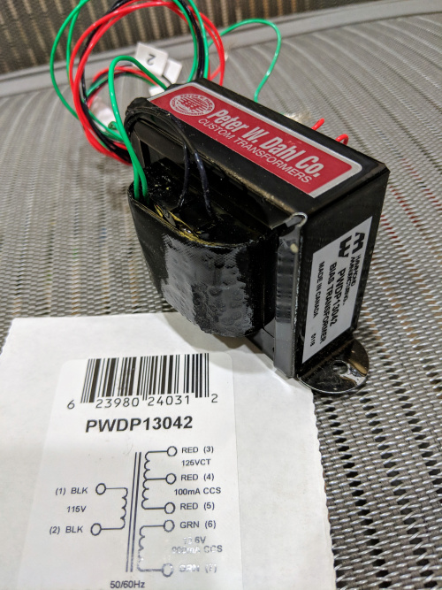
The replacement Peter Dahl transfomer! It took 2-1/2 months from initiating the order, until delivery. I made the actual purchase through Digi-Key, who provided the customer-facing fulfilment for Hammond. The transfomer also includes a 12.6VAC (at 800ma continuous commercial service) winding, which is used for three distinct purposes within the 30S-1:
- the AC voltage from this winding powers the incandescent dial and meter bulbs
- rectified and filtered DC runs through the HV-interlock circuit
- rectified and filtered DC is used to operate the Antenna Relays (when an external short-to-ground occurs - often an Amp T/R relay inside the exciter)
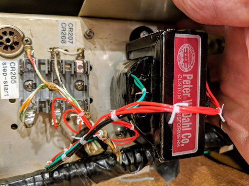
T203 installed, laced and soldered into it's new home!
When I look at the previous T203, especially the type of insulation and the under-chassis un-laced wiring, it makes me wonder if my burned T203 was already a replacement...? Hmmm... I will thoroughly check each and every circuit associated with this transformer, because it seems possible that this BIAS transformer, in this amp, has been an on-going issue. I intend to firmly quash all the problems now!
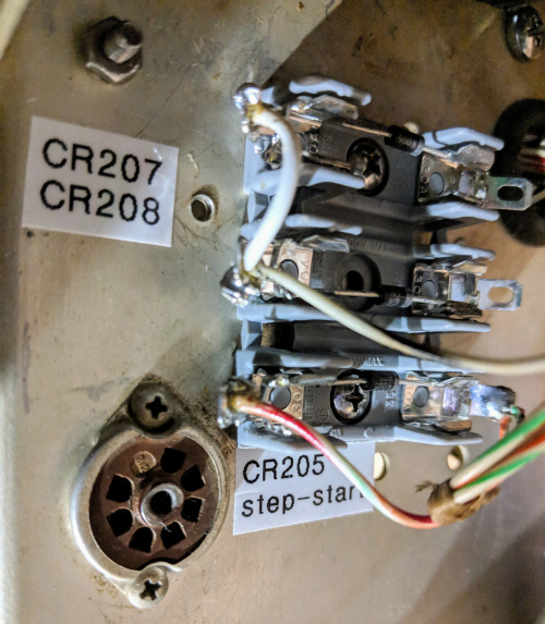
The original selenium rectifiers were long-gone, having been replaced with a terminal-strip and newer silicon diodes. Rather than replace or simply fix what was already there, I wanted to prevent another bent-and-shorted kind of tragedy (if it can happen once...).
I borrowed Collins' own idea from their nearby 12V rectifiers: I bought a triple-fuse mounting block (designed for AGC tubular glass fuses), and mounted my replacement 1N4005 diodes to this fuse-holder. The diode-leads were lightly clinched, then soldered to the fuse-clips, while the circuit connections were made to the holder's solder-tabs.
These diodes aren't going anywhere! And the printed component-labelling may help me (or someone else) in the future.
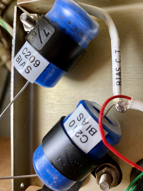
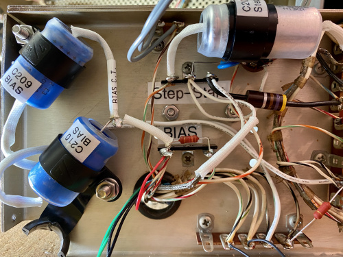
C209 and C210 upgraded, mechanically secured, and labelled A pair of new capacitors - same 50uF, but uprated from 150VDC to 250VDC, working temperature range -20C to +85C. The capacitors are labelled, as is the T203 Bias-Transformer centre-tap connection (I may be the next person helped by this clear labelling!). An additional layer of clear heat-shrink was added to ensure HV sturdiness, and the nylon mounting clamps are spaced a further 8mm off the chassis.
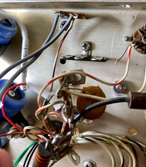
I broke this brittle terminal-strip.
While working underneath the Relay Shelf, I broke a terminal-strip. Unable to find an exact replacement, I opted for two smaller terminal-strips, turned 90-degrees to the original. And, this allowed me to neatly separate the two functions on the original: the Step-Start circuit, and the BIAS connections.
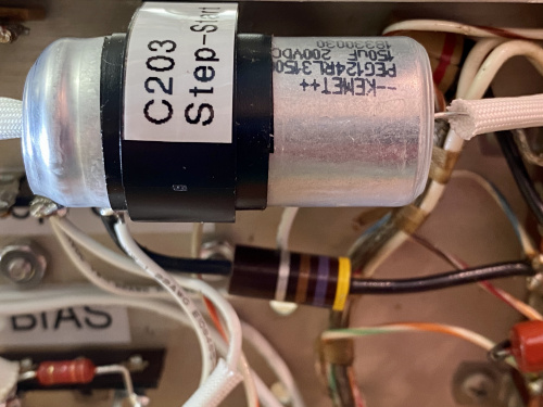
Replacement C203 step-start capacitor, securely mounted.
I replaced C203, making sure it's well-secured, and well-insulated. There should never be a problem of fat-fingers causing future short-circuits! The new C203 is rated at 200VDC, which improves on the original 150VDC rating, especially comforting considering how the incoming AC line-voltage has increased over the decades: designed with 115VAC/230VAC in mind, my current voltage is ~6% higher at 122/244 (just measured it).
Underside of Relay Shelf, now tidied.
Whew! All the parts I indicated on the schematic with yellow arrows have now been replaced - YAY! Now, on to some of the upgrades...
