Updates and Changes: Difference between revisions
| Line 19: | Line 19: | ||
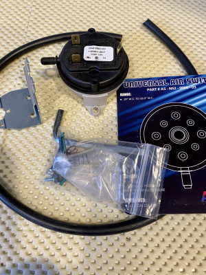
This alone will ensure tube-safety, but let's go even farther - let's use both belts, and suspenders :-) Modelling my Dayton-motored blower suggests the blower will produce somewhere around 0.8 inches water-column (wc) with the 4CX1500B. The published requirements for the 4CX1000A pressure is 0.2"wc at a full 1kW dissipation; the 4CX1500B requires even less at 0.18"wc for 1kW dissipation! And normal operation will duty-cycle / time-average the dissipation down. |
This alone will ensure tube-safety, but let's go even farther - let's use both belts, and suspenders :-) Modelling my Dayton-motored blower suggests the blower will produce somewhere around 0.8 inches water-column (wc) with the 4CX1500B. The published requirements for the 4CX1000A pressure is 0.2"wc at a full 1kW dissipation; the 4CX1500B requires even less at 0.18"wc for 1kW dissipation! And normal operation will duty-cycle / time-average the dissipation down. |
||
So, we'll sense the air-pressure at the base of the tube. Again, we have a wide window to allow full operation, and also maintain total tube safety. |
So, we'll sense the air-pressure at the base of the tube. Again, we have a wide window to allow full operation, and also maintain total tube safety. 0.1"wc should be "sufficient" for normal operation; 0.3"wc should allow for "no-time-limit" 1kW dissipation |
||
Thanks to induced-draft furnaces and hot-water-heaters, the HVAC industry has a wide selection of suitable temperature- and pressure-sensors. On the other hand, the Collins sensor is UnObtainium, and mine doesn't appear to be working correctly. We can now have <b>deterministic, sustainable, reproducible and improved</b> tube safety! |
Thanks to induced-draft furnaces and hot-water-heaters, the HVAC industry has a wide selection of suitable temperature- and pressure-sensors. On the other hand, the Collins sensor is UnObtainium, and mine doesn't appear to be working correctly. We can now have <b>deterministic, sustainable, reproducible and improved</b> tube safety! |
||
<gallery class="center" caption="Thermal and Pressure switches to replace Collins Overtemp K102"widths="400px" heights="400px" > |
|||
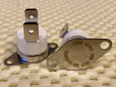
File:160degC_nc_thermal_switch.jpeg |
|||
File:adjustable_pressure_switch.jpeg |
|||
</gallery> |
|||
Revision as of 22:51, 28 May 2020
Raising CW Plate- and Screen-Voltages
Collins' reduction in High Voltage and Screen Voltage when using CW mode held back the 4CX1500B gain, and total-power. I was almost at the point of using the SSB setting for CW (as many do), when Chet VE3CFK pointed out...
That feeding both the primary wires from the front-panel-switch to the SSB connections on the transformer would give me a constant 3kV plate-voltage, and the elevated screen-voltage, no matter the mode. In fact, doing this means the only difference between SSB and CW is the negative grid-bias, and the resulting Class of operation.
The realization of Chet's suggestion: simply moving the CW-primary-power wire from Term #1 to Term #2, and similarly moving Term #6 to Term #5:

Now I have good gain and total power! Thanks, Chet! Here's a view of comfortable operating conditions now, for CW:

Thermal Overload Switch K102
My thermal sensor kicked my amp offline a couple of times, at only modest power-levels. Perhaps decades of time have taken their toll on the sensor; perhaps tube-changes have un-calibrated it; certainly my blower-motor-change will have altered it's response. The purpose of the thermal sensor: to open the HV-enable 12V circuit and K203 (primary AC power) if the tube gets too hot. The tube can get too hot with either excess dissipation, or lack of cooling-airflow.
The original sensor is kind of neat: it features a (self-)heater, which biases the thermal-switch up toward nearly opening... at this point, a delicate dance ensues: heat-calories from the tube try to open the switch, while heat-calories are removed by the blower-airflow.
BUT - it does not need to be such a delicate dance - the tube anode-seals require <250degC, and should be operated <225degC; in my prudence I think <200C should be safer. Infrared/laser remote temperature measurements suggest the tube may only rise xxxdegC above ambient, providing a very large margin, and a large window between "operation" and "danger". My solution will be a thermal-switch, which will open the 12V and K203 when it senses 160degC - ample safety for the tube, but not being a nagging nanny to the operator :-)
This alone will ensure tube-safety, but let's go even farther - let's use both belts, and suspenders :-) Modelling my Dayton-motored blower suggests the blower will produce somewhere around 0.8 inches water-column (wc) with the 4CX1500B. The published requirements for the 4CX1000A pressure is 0.2"wc at a full 1kW dissipation; the 4CX1500B requires even less at 0.18"wc for 1kW dissipation! And normal operation will duty-cycle / time-average the dissipation down.
So, we'll sense the air-pressure at the base of the tube. Again, we have a wide window to allow full operation, and also maintain total tube safety. 0.1"wc should be "sufficient" for normal operation; 0.3"wc should allow for "no-time-limit" 1kW dissipation
Thanks to induced-draft furnaces and hot-water-heaters, the HVAC industry has a wide selection of suitable temperature- and pressure-sensors. On the other hand, the Collins sensor is UnObtainium, and mine doesn't appear to be working correctly. We can now have deterministic, sustainable, reproducible and improved tube safety!
- Thermal and Pressure switches to replace Collins Overtemp K102
-
-