Dealing with the RF Output: Difference between revisions
No edit summary |
No edit summary |
||
| Line 23: | Line 23: | ||
The final touch was the addition of a right-angle PL-259-to-SO-239 adapter out the back; this allows my RF cable to tuck neatly down the back of the amplifier. |
The final touch was the addition of a right-angle PL-259-to-SO-239 adapter out the back; this allows my RF cable to tuck neatly down the back of the amplifier. |
||
[[Repair|Back to Repair]] |
|||
[[BIAS Transformer T203, and Associated Circuitry]] |
|||
Latest revision as of 17:44, 4 June 2020
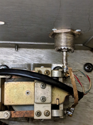
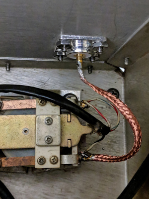
- Replacing Loose SO-239 Barrel Connector With Flanged SO-239
I unsoldered, and unscrewed the double-female SO-239 barrel-connector which arrived with my 30S-1 amplifier. The only good part was the use of wide copper-strapping for the rf-ouput. But the loose double-female connector flopped around and rotated whenever an antenna-connection was made, which in turn twisted and fatigued this wide copper strapping. Furthermore, the strapping was routed very close to the relay-frame and the low-voltage wiring.
I wasn't comfortable at all with the chassis-ground-connection provided by the wobbly and sloppy barrel connection - even if it "mostly worked", this could lead to one of those intermittent and puzzling annoyances, like fluctuating received-signals or flakey jumping of transmit plate-current.
I harvested some RG-8x-mini coax for it's braid to use as the RF output connection. Nominal operating conditions for this braid connection are expected to be in the neighbourhood of 300V and 5A - I have ample margin on both parameters. I twisted and pushed the braid all the way into the bottom of the SO-239 and soldered it prior to installing the connector to the chassis; I slightly opened the other end of the braid to allow a slip-fit all the way over the relay-terminal. The braided-conductor was then dressed neatly (angle of photo doesn't clearly show the 1/2-inch clearance to the chassis side-wall).
I connected my TS-850 transceiver to the RF Input, and my antenna to the RF Output. I received signals; pressing the top of the Antenna Changeover Relay K101 removed the signal.
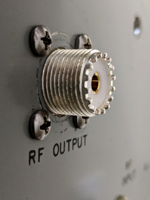
- New RF Output: Flanged SO-239
The flanged SO-239 features Teflon dielectric, silver-plating, and a gold-plated center-conductor. Mounting hardware is all 18-8 stainless: #6-32 x 3/8" Phillips pan-head machine-screws, internal-tooth lockwashers and hex-nuts. On the rear of the amplifier, I aligned the Phillips-head crosses :-)
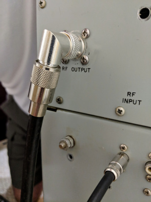
The final touch was the addition of a right-angle PL-259-to-SO-239 adapter out the back; this allows my RF cable to tuck neatly down the back of the amplifier.


