Testing: Difference between revisions
No edit summary |
|||
| Line 30: | Line 30: | ||
<ul> |
<ul> |
||
<li>use a paint-stir-stick, behind the fuse-panel, to wedge and hold open the HV short, and keep closed the 12VDC interlock switch. Eyes Open!</li></ul> |
<li>use a paint-stir-stick, behind the fuse-panel, to wedge and hold open the HV short, and keep closed the 12VDC interlock switch. Eyes Open!</li></ul> |
||
<p> |
|||
<span> |
|||
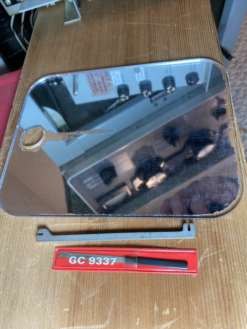
[[File:Relay_contact_adjust.jpg|500px|thumb|left|Contact adjustment tools: shaving mirror, burnisher, contact-bender]] |
|||
With the Relay Shelf flopped onto it's side, I determined that the rearmost contact of K203 was failing to close. I burnished the contacts, then adjusted both such that they close when the relay armature has moved about 2/3 of it's travel. |
|||
</span> |
|||
</p> |
|||
<br clear=all> |
|||
Revision as of 21:44, 29 June 2021
120V Initial Testing
- I installed the original 4CX1000A tube which came in my amplifier. Only the 3.2A fuse was installed, and I applied power!
- The meters illuminated; after the time-delay relay closed, the dials also illuminated. The "ON / OFF" switch functioned.
- Opening either the top-lid or the front-panel removed the dial-illumination, and prevented operation of the "ON / OFF" switch.
- I tested the Thermal Overload switch K102 by moving it out of, and back into the airstream - it works, and disables the "ON / OFF" switch when there is no airflow over the sensor.
The Safety and Control seem to work. The Bias and Filament adjustments work.
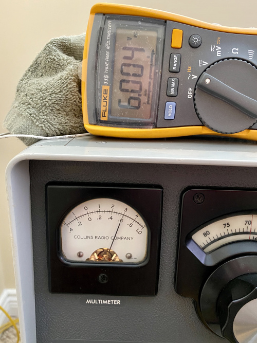
I clipped some test-leads right onto the tube-socket, in order to measure and adjust filament-voltage accurately. Eimac specifies 6.0 +/-5%, so that's what I gave it. The panel-meter actually reads the incoming 115VAC supply, using that as a proxy for the actual filament voltage - you can see this does a pretty good job.
With an eye on the amp, I ran it this way for 8 hours, to getter the tube. And to verify that the blower doesn't go into thermal-shutdown. And to get the various smells flushed out (especially that new Dayton motor - it runs quite hot).
240V Testing
After warm-up, I pressed "ON", and got a nice "clunk" from relay K203. But no High Voltage :-( I metered and monitored the primary AC windings of Transformer T201 - nothing! That pretty much points to K203 as the culprit. Out came the Relay Shelf, for a focussed look. Removal notes:
- Remove the bakelite AC power cover, and disconnect all the power leads
- Remove the 5 front / 2 rear screws, and shift the Shelf over - to allow removal of the HV shorting wire (hidden behind edge of compartment)
Servicing Note:
- use a paint-stir-stick, behind the fuse-panel, to wedge and hold open the HV short, and keep closed the 12VDC interlock switch. Eyes Open!
With the Relay Shelf flopped onto it's side, I determined that the rearmost contact of K203 was failing to close. I burnished the contacts, then adjusted both such that they close when the relay armature has moved about 2/3 of it's travel.

