Testing
120V Initial Testing
- I installed the original 4CX1000A tube which came in my amplifier. Only the 3.2A fuse was installed, and I applied power!
- The meters illuminated; after the time-delay relay closed, the dials also illuminated. The "ON / OFF" switch functioned.
- Opening either the top-lid or the front-panel removed the dial-illumination, and prevented operation of the "ON / OFF" switch.
- I tested the Thermal Overload switch K102 by moving it out of, and back into the airstream - it works, and disables the "ON / OFF" switch when there is no airflow over the sensor.
The Safety and Control seem to work. The Bias and Filament adjustments work.

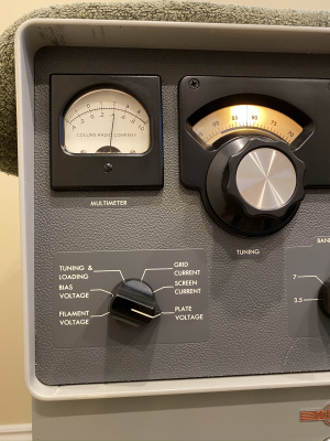
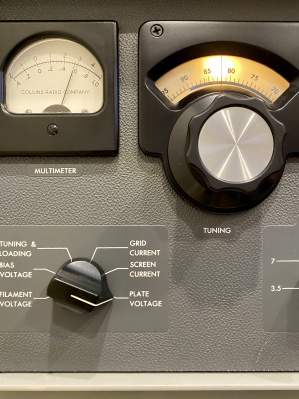
I clipped some test-leads right onto the tube-socket, in order to measure and adjust filament-voltage accurately. Eimac specifies 6.0 +/-5%, so that's what I gave it. The panel-meter actually reads the incoming 115VAC supply, using that as a proxy for the actual filament voltage - you can see this does a pretty good job.
With an eye on the amp, I ran it this way for 8 hours, to getter the tube. And to verify that the blower doesn't go into thermal-shutdown. And to get the various smells flushed out (especially that new Dayton motor - it runs quite hot).
240V Testing
After warm-up, I pressed "ON", and got a nice "clunk" from relay K203. But no High Voltage :-( I metered and monitored the primary AC windings of Transformer T201 - nothing! That pretty much points to K203 as the culprit. Out came the Relay Shelf, for a focussed look. Removal notes:
- Remove the bakelite AC power cover, and disconnect all the power leads
- Remove the 5 front / 2 rear screws, and shift the Shelf over - to allow removal of the HV shorting wire (hidden behind edge of compartment)
Servicing Note:
- use a paint-stir-stick, behind the fuse-panel, to wedge and hold open the HV short, and keep closed the 12VDC interlock switch. Eyes Open!

With the Relay Shelf flopped onto it's side, I determined that the rearmost contact of K203 was failing to close. I burnished the contacts, then adjusted both such that they close when the relay armature has moved about 2/3 of it's travel.
- Measuring Per-Mode Plate Voltages
-
 CW Plate Voltage: 2050VDC
 -
 SSB Plate Voltage: 2750V


Quick test: I couldn't get any plate-idle-current. Recall, I had pre-set the BIAS Voltage to -60V, to be on the conservative side and start out with a reduced idle-current. But now, I had no idle-current. A further quick test showed infinite input-SWR for the exciter. Two problems to look into...
So, next step: let's thoroughly check screen supply circuitry.
I got my 12VDC bench-supply, and verified the switching of K205, and also that K101 would also trigger K205. Both were good. Basic ohmmeter checking showed connectivity from the screen supply to the cathode-chock L103. Hmmm... let's thoroughly check the AC and DC values related to the Screen supply.

I got three meters, and carefully measured:
- AC input voltage on primary of T201, after fuses, switches, relays and wiring: 240VAC
- AC output voltage from Screen secondary of T201: 260VAC
- DC output of the Screen supply, across C204: 235.2VDC
We have connectivity, we have all voltages. Hmmm... maybe I just have to crank harder on the BIAS Adjustment. So, I did. I managed to achieve the prescribed 200mA idle-current in SSB mode, but only when the BIAS was down to -36V! I wonder if my tube is nearly-shot?
Now... RF in! But wait - I have infinite input SWR?!?! :-(
I metered every cable and connection along the RF input path, and found that the culprit was K205 at the back of the power compartment. It appears that my burning T203 deposited a tarry film on the open contacts. After cleaning, I tested K205 only - now good! Along the path of debugging, I removed and cleaned the input band-switch (cut strips of bond paper, spray contact-cleaner on the strips, use tweezers to sneak the paper between the contacts and drag it through).
RF in now brings RF out, but it isn't very impressive with this particular tube. Roughly, I drove it with 50W CW input, 900W DC to the final, and 400W out. As I increased the drive, I began to note slight movement toward -0.2mA grid-current... this tube simply wasn't going to give anything more. Time to get Contestant #2 - a 1979 used 4CX1000A which looked a lot less darkened and still has Eimac paint on it.
A day later...
Tube #2 is much better - I obtained a gain of about 7.3: 75W RF input drive, 900W DC plate input, 550W RF output to the dummy-load. I'll set this aside as a tested spare.