File list
Jump to navigation
Jump to search
This special page shows all uploaded files.
| Date | Name | Thumbnail | Size | User | Description | Versions |
|---|---|---|---|---|---|---|
| 17:57, 12 August 2020 | Dead cr216.jpg (file) | 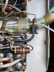 |
2.48 MB | Gordonp | Gord - original, non-functional top-hat CR216 | 1 |
| 17:53, 12 August 2020 | Bulb mod cable lacing.jpg (file) | 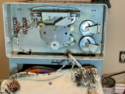 |
3.91 MB | Gordonp | Gord - image showing dial-lamp mod, to illuminate after warm-up complete | 1 |
| 17:46, 12 August 2020 | 12v safety control working.jpg (file) | 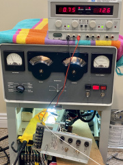 |
2.62 MB | Gordonp | Gord - 30s-1 final test showing all 12V Safety/Control working | 1 |
| 17:34, 12 August 2020 | Improved dial lighting.jpg (file) | 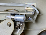 |
2.14 MB | Gordonp | Gord - 30s-1 improved dial lighting, with insulation and sleeving | 1 |
| 17:33, 12 August 2020 | 12v lamp short.jpg (file) | 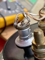 |
2.3 MB | Gordonp | Gord - 30s-1 meter-lamp short | 1 |
| 17:30, 12 August 2020 | 12v safety interlock test.jpg (file) | 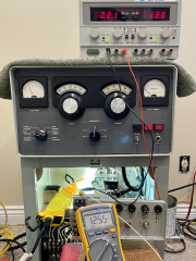 |
2.15 MB | Gordonp | Gord - testing 30s-1 12V safety interlock | 1 |
| 17:29, 12 August 2020 | 12v control test.jpg (file) | 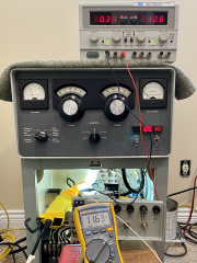 |
2.24 MB | Gordonp | Gord - Testing 12V control circuitry | 1 |
| 20:45, 23 July 2020 | Screen HV resistor check.jpg (file) | 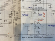 |
3.27 MB | Gordonp | Gord - annoted schematic showing screen-supply resistance checks | 1 |
| 20:42, 23 July 2020 | Screen c204 repaired.jpg (file) | 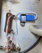 |
2.67 MB | Gordonp | Gord - replacement C204 screen filter capacitor | 1 |
| 20:40, 23 July 2020 | Screen c204 orig.jpg (file) | 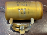 |
601 KB | Gordonp | Gord - original C204 screen-supply filter capacitor | 1 |
| 20:37, 23 July 2020 | Repaired screen rect.jpg (file) | 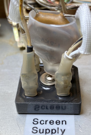 |
1.65 MB | Gordonp | Gord - new modular diode-bridge for screen supply | 1 |
| 20:34, 23 July 2020 | Burned screen rect.jpg (file) | 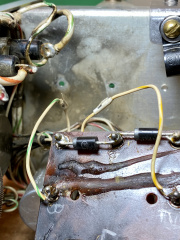 |
2.49 MB | Gordonp | Gord - screen supply board and blackened chassis beneath, as it came to me | 1 |
| 20:08, 6 July 2020 | 1n5711 tuneload pcb.jpeg (file) | 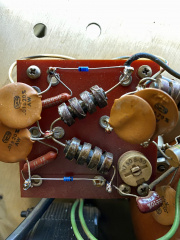 |
2.66 MB | Gordonp | Gord - 1N5711 diodes installed on Tune/Load circuit-board | 1 |
| 20:06, 6 July 2020 | Original tuneload pcb.jpeg (file) | 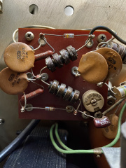 |
3.47 MB | Gordonp | Original Tune/Load sensing circuit-board | 1 |
| 18:49, 14 June 2020 | Air sense hose under boot.jpeg (file) | 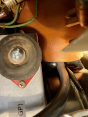 |
2.11 MB | Gordonp | Gord - Air-Pressure sensing tube simply stuck up between blower nozzle, and flexible coupling-boot | 1 |
| 17:13, 5 June 2020 | Toroids.jpg (file) | 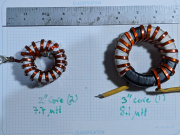 |
2.85 MB | Kb3bf | 1 | |
| 17:46, 4 June 2020 | Biasdiodes mounted fuseholder.jpg (file) | 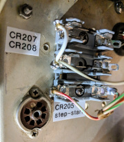 |
2.49 MB | Gordonp | Gord - bias diodes mounted on fuse-holder | 1 |
| 17:42, 4 June 2020 | 30s1 flanged so239 rfout rightangle.jpg (file) | 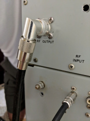 |
2.2 MB | Gordonp | Gord - right-angle PL-259-to-SO-239 adapter out the back | 1 |
| 17:41, 4 June 2020 | 30s1 flanged so239 rfout exterior.jpg (file) | 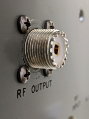 |
1.68 MB | Gordonp | Gord - flanged SO-239 features Teflon dielectric, silver-plating, and a gold-plated center-conductor | 1 |
| 17:37, 4 June 2020 | 30s1 flanged so239 rfout.jpg (file) | 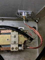 |
2.22 MB | Gordonp | Gord - New teflon and gold flaged SO-239 | 1 |
| 17:35, 4 June 2020 | 30s1 sloppy s0239 barrel rfout.jpg (file) | 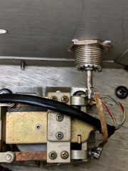 |
2 MB | Gordonp | Gord - as-acquired sloppy and soldered SO-239 barrel-connector | 1 |
| 17:27, 4 June 2020 | C203 step start.jpg (file) | 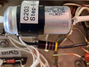 |
2.17 MB | Gordonp | Gord - Replacement C203 step-start capacitor, securely mounted | 1 |
| 17:22, 4 June 2020 | Whoops terminal strip.jpg (file) | 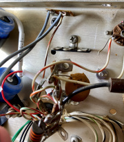 |
2.54 MB | Gordonp | Gord - broken brittle terminal-strip | 1 |
| 17:20, 4 June 2020 | C209 c210.jpg (file) | 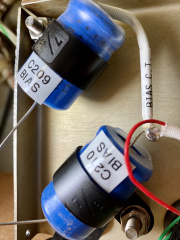 |
2.34 MB | Gordonp | Gord - C209 and C210 upgraded, mechanically secured, and labelled | 1 |
| 17:11, 4 June 2020 | 30s1 t203 laced installed.jpg (file) | 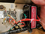 |
2.71 MB | Gordonp | Gord - T203 installed, laced and soldered in | 1 |
| 17:09, 4 June 2020 | 30s-1 replacement bias transfomer.jpg (file) | 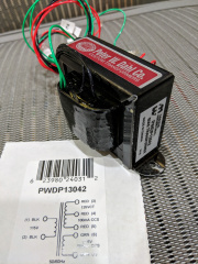 |
2.93 MB | Gordonp | Gord - new Hammond PWDP-13042 bias-supply replacement transformer | 1 |
| 00:08, 4 June 2020 | 30S1 HV shot 2.jpg (file) | 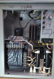 |
3.09 MB | VE3CFK | 1 | |
| 00:07, 4 June 2020 | 30S1 HV shot 1.jpg (file) | Error creating thumbnail: File with dimensions greater than 12.5 MP |
4.09 MB | VE3CFK | 1 | |
| 00:03, 4 June 2020 | 30S1 front view.jpg (file) | 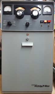 |
2.74 MB | VE3CFK | 1 | |
| 22:24, 1 June 2020 | Underside relayshelf tidy.jpg (file) | 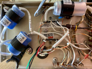 |
3.44 MB | Gordonp | Gord - Underside View of the Relay Shelf | 1 |
| 21:58, 1 June 2020 | 30s1 decrepit T202.jpg (file) | 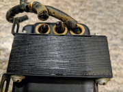 |
3.17 MB | Gordonp | Gord - Filament transfomer T202 with broken leads | 1 |
| 17:47, 1 June 2020 | Thermal sensor mount testfitting.jpeg (file) | 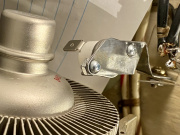 |
1.88 MB | Gordonp | Gord - test fitting the final iteration of the thermal-sensor mount | 1 |
| 17:45, 1 June 2020 | Sensor bracket prototype evolution.jpeg (file) | 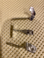 |
3.8 MB | Gordonp | Gord - a series of thermal-sensor bracket-prototypes | 1 |
| 17:43, 1 June 2020 | Coffeecan snips pliers bracket making.jpeg (file) | 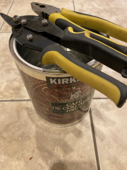 |
681 KB | Gordonp | Gord - the Costco coffee-can, tin-snips and pliers for making a new sensor-bracket | 1 |
| 17:21, 1 June 2020 | Thermal overload switch k102.jpeg (file) | 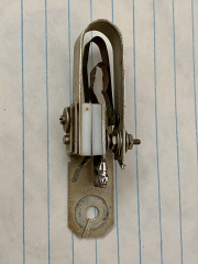 |
2.29 MB | Gordonp | Gord - removed, original Collins thermal-overload switch K102 | 1 |
| 17:11, 1 June 2020 | Top view pressure temp sensors.jpeg (file) | 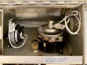 |
2.8 MB | Gordonp | Gord - Top View of the RF Compartment, Again Showing Thermal-Safety | 1 |
| 17:10, 1 June 2020 | Rear view pressure temp sensors.jpeg (file) | 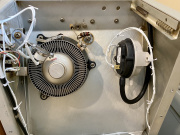 |
2.56 MB | Gordonp | Rear View of the RF Compartment, Showing New Thermal-Safety | 1 |
| 22:47, 28 May 2020 | Adjustable pressure switch.jpeg (file) | 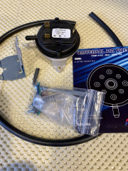 |
3.99 MB | Gordonp | Gord - an adjustable pressure-switch from HVAC industry | 1 |
| 22:46, 28 May 2020 | 160degC nc thermal switch.jpeg (file) | 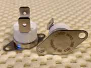 |
2.62 MB | Gordonp | Gord - self-resetting 160deg thermal switch | 1 |
| 00:29, 28 May 2020 | Cw operation boosted HV screen.jpeg (file) | 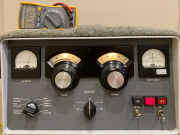 |
2.67 MB | Gordonp | Gord - photo showing CW operation with boosted HV and screen. | 1 |
| 00:24, 28 May 2020 | HV screen always at SSB.jpeg (file) | 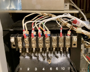 |
1.74 MB | Gordonp | Gord - the T201 Transformer connections required to provide higher HV in both SSB and CW modes | 1 |
| 00:16, 28 May 2020 | Spare fuses and bristol.jpeg (file) | 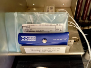 |
2.33 MB | Gordonp | Gord - a set of spare fuses and Bristol wrenches on the Power Supply Shelf | 1 |
| 16:47, 26 May 2020 | 160m vna s11.jpg (file) | 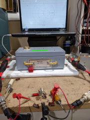 |
3.88 MB | Gordonp | Chris - VNA showing S11 for 160m input-circuit | 1 |
| 16:45, 26 May 2020 | 160m input wafer mods2.jpg (file) | 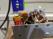 |
3.42 MB | Gordonp | Chris - input-switch-wafer mods 2nd view, for 160m | 1 |
| 16:43, 26 May 2020 | 160m input wafer mods.jpg (file) | 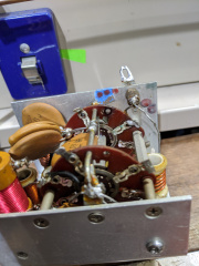 |
3.27 MB | Gordonp | input-switch-wafer modifications for 160m | 1 |
| 16:41, 26 May 2020 | 160m vacuum relay.jpg (file) | 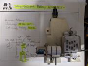 |
5.47 MB | Gordonp | rotated, for upright / readable viewing | 2 |
| 16:31, 26 May 2020 | Switch wafer arrow.jpg (file) | 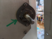 |
10.27 MB | Gordonp | Chris - 160m switch wafer with arrow | 1 |
| 16:26, 26 May 2020 | Input switch wafer.jpg (file) | 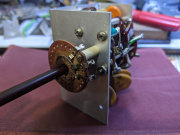 |
5.13 MB | Gordonp | Chris - 160m new, added input-switch wafer | 1 |
| 15:49, 26 May 2020 | Pa.jpg (file) | 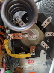 |
6.29 MB | Gordonp | Chris - PA 160m switch wafer | 1 |
| 15:47, 26 May 2020 | Waf.jpg (file) | 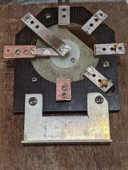 |
3.52 MB | Gordonp | Chris - 160m PA switch-wafer | 1 |