Repair: Difference between revisions
Jump to navigation
Jump to search
(Created page with "I printed the schematics, figured out how to remove the Relay Shelf, and began: * Bias Transformer T203 was utterly toasted... burned and bubbled. Fortunately Peter Dahl / Ha...") |
No edit summary |
||
| Line 1: | Line 1: | ||
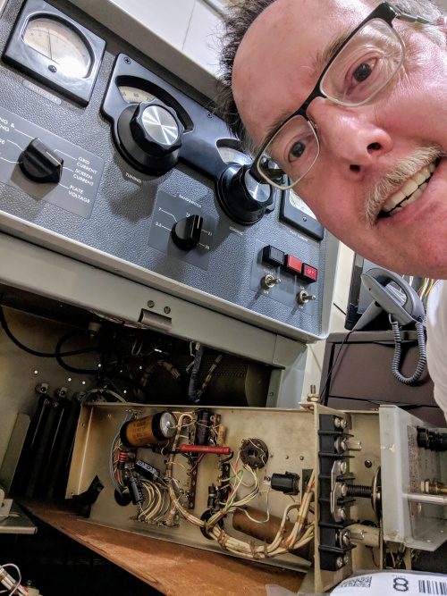
I printed the schematics, figured out how to remove the Relay Shelf, and began: |
I printed the schematics, figured out how to remove the Relay Shelf, and began: |
||
[[File:30s1_relayshelf_halfout_selfie.jpg|500px|thumb|center]] |
|||
* Bias Transformer T203 was utterly toasted... burned and bubbled. Fortunately Peter Dahl / Hammond offer a top-quality replacement - Whew! Nearby components and the wiring-harness appeared miraculously undamaged! |
* Bias Transformer T203 was utterly toasted... burned and bubbled. Fortunately Peter Dahl / Hammond offer a top-quality replacement - Whew! Nearby components and the wiring-harness appeared miraculously undamaged! |
||
* Bias rectifiers had been changed to silicon diodes, mounted on a terminal-strip. However, the terminal-strip was bent over, shorting at least one (perhaps two) leads to the chassis. |
* Bias rectifiers had been changed to silicon diodes, mounted on a terminal-strip. However, the terminal-strip was bent over, shorting at least one (perhaps two) leads to the chassis. |
||
Revision as of 18:13, 21 May 2020
I printed the schematics, figured out how to remove the Relay Shelf, and began:
- Bias Transformer T203 was utterly toasted... burned and bubbled. Fortunately Peter Dahl / Hammond offer a top-quality replacement - Whew! Nearby components and the wiring-harness appeared miraculously undamaged!
- Bias rectifiers had been changed to silicon diodes, mounted on a terminal-strip. However, the terminal-strip was bent over, shorting at least one (perhaps two) leads to the chassis.
- In a similar vein on the underside of the Relay Shelf, Bias divider resistor R218 was bent to touch the chassis
- Next to this bent/touching resistor, I then saw the cracked-and-broken 10-ohm R232 (limits screen-supply inrush current).
- And, the RF output connector had been changed from the N-flanged original, to a loose-and-sloppy SO-239 barrel (featuring mangled threads which prevented tightening).
- Time-delay thermal relay K202 was only 35-seconds, not 3-minutes as Collins designed (to ensure V101's cathode is properly heated before use).
- Rectifier-filament transformer T202 had cracked-and-broken secondary leads. Because this amplifier had replacment solid-state HV rectifiers, I decided to simply remove the no-longer-needed T202.
Here is a photo of the taped-up schematic, with my annotations and some flags showing the components I decided to replace:
