160m Mods: Difference between revisions
No edit summary |
No edit summary |
||
| Line 24: | Line 24: | ||
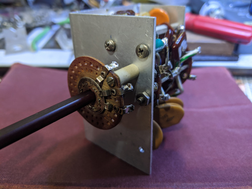
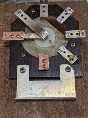
[[File:160m_input_wafer_mods.jpg|500px|thumb|center|input-switch-wafer modifications for 160m]] |
[[File:160m_input_wafer_mods.jpg|500px|thumb|center|input-switch-wafer modifications for 160m]] |
||
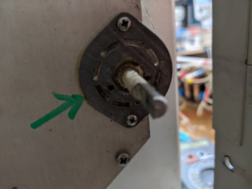
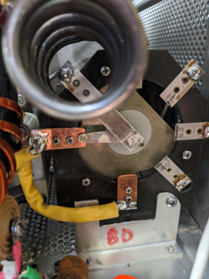
[[File:160m_input_wafer_mods2.jpg|500px|thumb|center|input-switch-wafer mods 2nd view, for 160m]] |
[[File:160m_input_wafer_mods2.jpg|500px|thumb|center|input-switch-wafer mods 2nd view, for 160m]] |
||
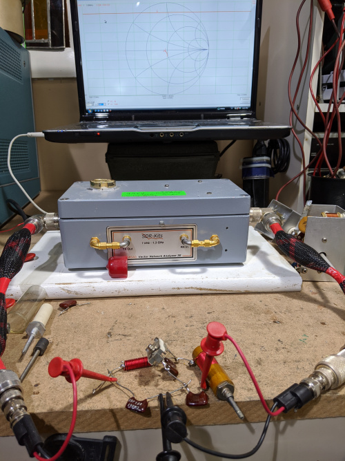
[[File:160m_vna_s11.jpg|500px|thumb|center|VNA showing S11 for 160m input-circuit]] |
|||
Revision as of 16:48, 26 May 2020
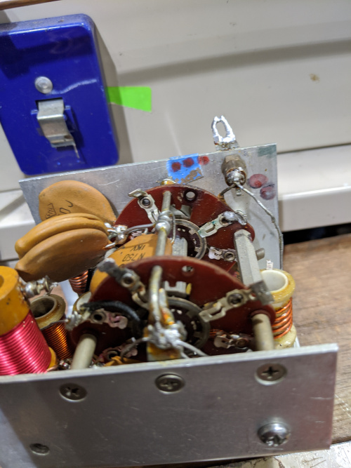
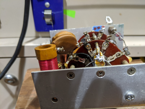
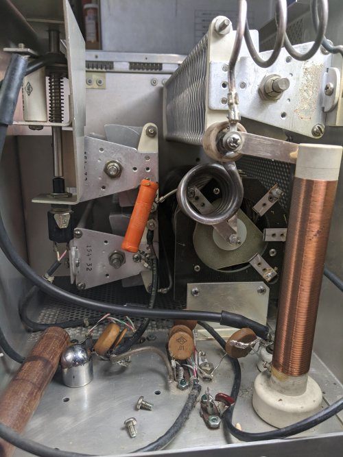
160m input circuit S11 after final values were optimized. It's a tight fit inside the input circuit compartment. 160m variable coil is bottom left. The other160m coil and SM caps are tucked inside the aluminum box.
NB. It appears there are two different 30S1 input circuits depending on the age of the amp. The 160m mod is practical only for input circuits using simple wafers with contacts on one side only. If there is a grounding ring in addition to a selector ring then things get rather complicated. The mod I am doing does not deal with the double sided grounding wafers for obvious complex fabrication reasons.
Also it is my intention to upgrade to 1 KV SM if I can find any (I am using 500V). Collins uses 1KV disk ceramic. I tested 500V SMs i am using and they showed no leakeage up to 1.5KV, the max range on the 576 Tek curve tracer, so they maybe ok under 100W. I noticed Alpha 77Sx uses compression micas, which have higher Q than ceramics.
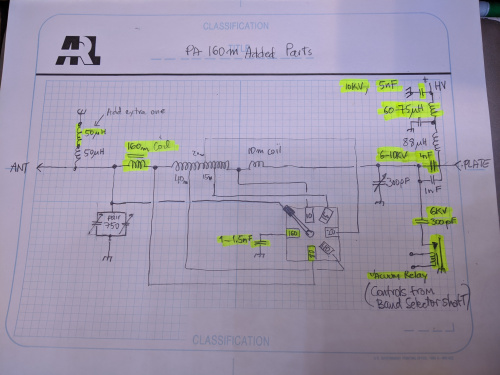
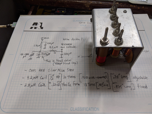
- Switch-Wafer modifications
