How and Why I Changed It: Difference between revisions
m Gordonp moved page How I Did It to How I Changed It |
No edit summary |
||
| Line 13: | Line 13: | ||
File:adjustable_pressure_switch.jpeg|All-Temp NS2-0000-03 Universal Air-Pressure Switch. RobertShaw 2374-510 looks similar |
File:adjustable_pressure_switch.jpeg|All-Temp NS2-0000-03 Universal Air-Pressure Switch. RobertShaw 2374-510 looks similar |
||
</gallery> |
</gallery> |
||
==Comment== |
|||
Anecdotally, the adjustment procedure for the K102 thermal switch is to run the amp at full-power, then tweak R106 until it just shuts down. But following this means 1kW DC input to the tube, and about 500W dissipation. At this dissipation level, with the stock blower's airflow, the anode temperature rises by xxxdegC.... far, far below damaging levels. I conclude that this sensor is not factory-set to save the tube, but rather to prevent the operator from exceeding the designed power-level. Saving the tube is a side-effect. I will re-prioritize, and make tube-safety paramount. |
|||
Revision as of 16:56, 1 June 2020
The original Collins thermal sensor is kind of neat: It's a normally-closed thermal switch with a heater, which biases the thermal-switch up toward nearly opening... at this point, a delicate dance ensues: heat-calories from the tube try to open the switch, while heat-calories are removed by the blower-airflow.
BUT - it does not need to be such a delicate dance - the tube anode-seals require <250degC, and should be operated <225degC; in my prudence I think <200C should be safer. Infrared/laser remote temperature measurements suggest the tube may only rise xxxdegC above ambient, providing a very large margin, and a large window between "operation" and "danger". My solution will be a thermal-switch, which will open the 12V and K203 when it senses 160degC - ample safety for the tube, but not being a nagging nanny to the operator :-)
This alone will ensure tube-safety, but let's go even farther - let's use both belts, and suspenders :-) Modelling my Dayton-motored blower suggests the blower will produce somewhere around 0.8 inches water-column (wc) with the 4CX1500B. The published requirements for the 4CX1000A pressure is 0.2"wc at a full 1kW dissipation; the 4CX1500B requires even less at 0.18"wc for 1kW dissipation! And normal operation will duty-cycle / time-average the dissipation down.
So, we'll sense the air-pressure at the base of the tube. Again, we have a wide window to allow full operation, and also maintain total tube safety. 0.1"wc should be "sufficient" for normal operation; 0.3"wc should allow for "no-time-limit" 1kW dissipation (maybe my RTTY!).
Thanks to induced-draft furnaces and hot-water-heaters, the HVAC industry has a wide selection of suitable temperature- and pressure-sensors. On the other hand, the Collins sensor is UnObtainium, and mine doesn't appear to be working correctly. We can now have deterministic, sustainable, reproducible and improved tube safety!
- Thermal and Pressure switches to replace Collins Overtemp K102
-
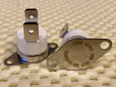 Honeywell 2455RC-90820388 SPST NC 160degC Auto-Reset Thermo-Switch
 -
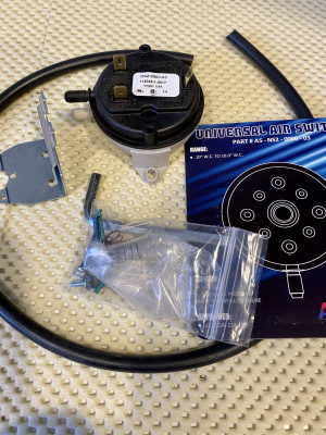 All-Temp NS2-0000-03 Universal Air-Pressure Switch. RobertShaw 2374-510 looks similar


Comment
Anecdotally, the adjustment procedure for the K102 thermal switch is to run the amp at full-power, then tweak R106 until it just shuts down. But following this means 1kW DC input to the tube, and about 500W dissipation. At this dissipation level, with the stock blower's airflow, the anode temperature rises by xxxdegC.... far, far below damaging levels. I conclude that this sensor is not factory-set to save the tube, but rather to prevent the operator from exceeding the designed power-level. Saving the tube is a side-effect. I will re-prioritize, and make tube-safety paramount.