Primary AC Wiring: Difference between revisions
No edit summary |
No edit summary |
||
| Line 30: | Line 30: | ||
<b><u>AC Primary Connection Change Revealed</b></u> |
<b><u>AC Primary Connection Change Revealed</b></u> |
||
<p>This Collins Radio memo explains the rationale for the AC Primary Wiring Change, and my confusion: Jumpering 2 to 3&4 serve to reduce cabinet-hum, for some 30s-1 amplifiers. Mine doesn't appear to suffer from this cabinet hum, so I'll leave terminal 2 disconnected (which I believe is more-sound, electrically). |
<p>This Collins Radio memo explains the rationale for the AC Primary Wiring Change, and my confusion: Jumpering 2 to 3&4 serve to reduce cabinet-hum, for some 30s-1 amplifiers. Mine doesn't appear to suffer from this cabinet hum, so I'll leave terminal 2 disconnected (which I believe is more-sound, electrically).</p> |
||
[[File:30S1_paper_figures06062020.pdf|500px|thumb|right]] |
[[File:30S1_paper_figures06062020.pdf|500px|thumb|right]] |
||
Revision as of 22:04, 13 August 2020
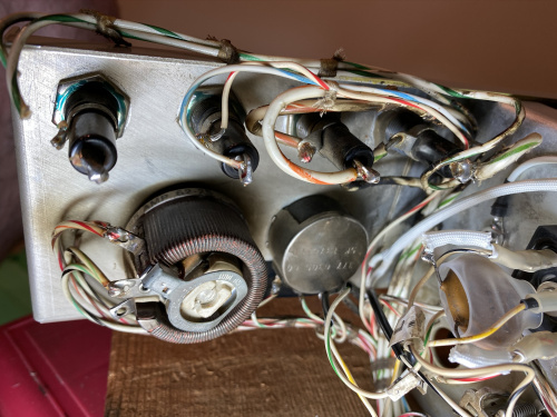
I am not happy with the charred and crispy wires in the corner near the fuses. I am also not very happy about cutting-back the nicely-marked factory wires. But balancing these two un-happinesses, I'll cut them back ~6" and re-make safe wiring.
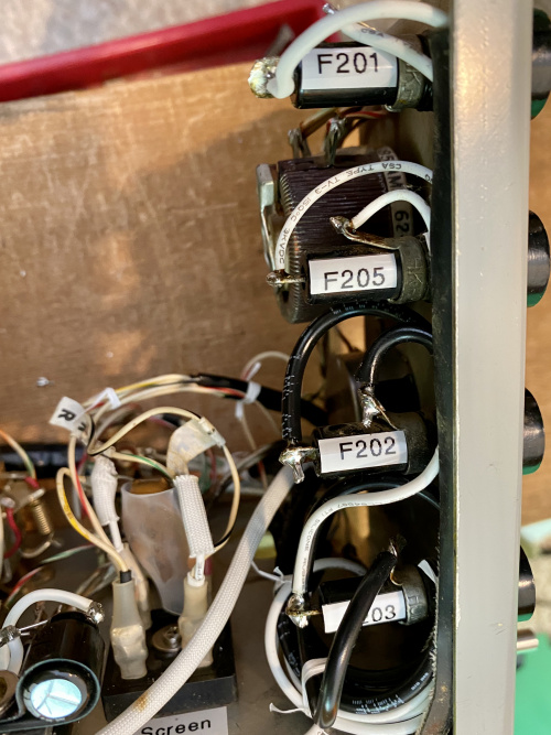
Ah - much better! Laced, placed, soldered and sleeved. The sleeve was harvested from the removed T202 (above), then split down the side; the idea is to prevent possible wire-chafe on the sharp edge of the fuse panel. I traced the wires before connecting, to ensure that the hot/supply circuit runs to the rear of the fuseholder, for safety when changing.
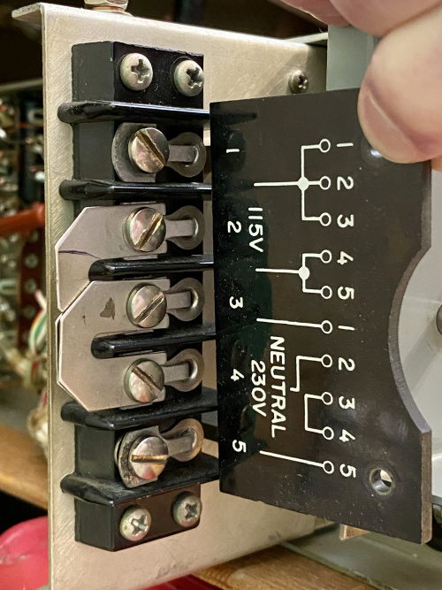
This one is interesting... I did look at the bakelite cover on the AC-input when I first brought it home. At any rate, the jumpers were hidden from view, behind the bakelite cover, and I ASSumed it was good-to-go for 240VAC. Seeing the actual jumpers now, and viewing the schematic while working on the fuses/wiring suggested an error. Deeper digging: the 1964 manul I am using differs from the later 1976 manual, for this connection. The Bakelite printing and my schematic do not jumper 2 to 3&4. But 1976 does. Connecting 2 to 3&4 would have forced the neutral (mid-point of my 240VAC) onto the center-connection of the two series-connected HV transformer primary windings. T201 never powered-up, but if it had, then this center-connection would have naturally been at the mid-point anyway.
Later, I pulled the fuses, and found one open-circuit. With the Terminal 2 jumpered as-pictured, the 1/2-primary with the open fuse would now act as a third secondary winding, and be live! The "real" secondaries would still be powered, allowing plate/screen to have some supply despite a blown primary fuse :-O
I am not quite sure what to think on this one...
AC Primary Connection Change Revealed
This Collins Radio memo explains the rationale for the AC Primary Wiring Change, and my confusion: Jumpering 2 to 3&4 serve to reduce cabinet-hum, for some 30s-1 amplifiers. Mine doesn't appear to suffer from this cabinet hum, so I'll leave terminal 2 disconnected (which I believe is more-sound, electrically).


