160m Mods: Difference between revisions
No edit summary |
No edit summary |
||
| Line 28: | Line 28: | ||
[[File:Schem.jpg|500px|thumb|center|Fig.5 Schematic showing 160m additions to the PA]] |
[[File:Schem.jpg|500px|thumb|center|Fig.5 Schematic showing 160m additions to the PA]] |
||
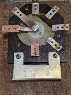
PA Plate location is to the right, antenna to the left; this to reflect the actual band settings as observed from the rear. It appears that the 80m and 160m tabs are connected, but they are not. A cutout of the mounting bracket is necessary to make room for the 80m tab. Tabs are 0.023" thick. |
|||
extra text here |
|||
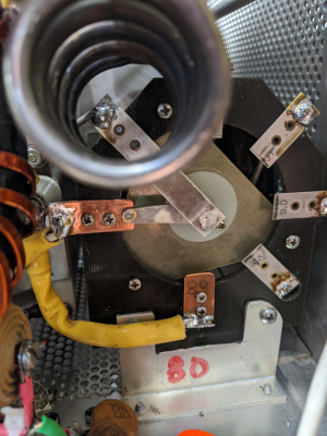
[[File:160m_ouptput_PA.jpg|500px|thumb|center|Fig.6 Clearing a path to the rear PA band wafer for removal]] |
[[File:160m_ouptput_PA.jpg|500px|thumb|center|Fig.6 Clearing a path to the rear PA band wafer for removal]] |
||
Revision as of 05:05, 27 May 2020
160m Mods. The 160m mods involve working on: 1. the input PI section, 2. the PA output PI section. 3. changing one of the bandswitch stops.
It's a tight fit inside the input circuit compartment. Facing the front, the 160m variable coil is mounted on the left side next to the 80m coil. The fixed coil and SM caps are tucked inside the semi closed aluminum box.
NB. It appears there are two different 30S1 input circuits depending on the age of the 30S-1 amp. The 160m mod is practical only for input circuits using simple wafers with contacts on one side only. If there is a grounding ring in addition to a selector ring then things get rather complicated. This mod does not deal with the double sided grounding wafers for obvious complex fabrication reasons. The wafers used in the 30S-1 are 45 degree type, next to impossible to find. The bakelite material is old and very easy to fracture. Utmost care is necessary to prevent breakage. The alternative is to make new blanks with FR40 board material a time consuming proposition.
Collins uses 1KV ceramic disk capacitors for the other bands, ideally the 160m capacitors should be 1 KV SM but space is tight. The 500V SMs i showed no leakage up to 1.5KV, and should should be ok up to 100W 3-1 SWR. Alpha 77Sx uses compression silver micas, which have higher Q than ceramics.

extra text here

extra text here

extra text here

extra text here

PA Plate location is to the right, antenna to the left; this to reflect the actual band settings as observed from the rear. It appears that the 80m and 160m tabs are connected, but they are not. A cutout of the mounting bracket is necessary to make room for the 80m tab. Tabs are 0.023" thick.

extra text here
- PA-Wafer. Adding 80m and 160m tabs
-
-


extra text here

extra text here

Jennings F4B-26S is a 26V DC latching relay with two 7 Ohms coils. It requires a 26V DC pulse to switch from ON to OFF and viceversa. A pair of 555 timers could be set up, but they require additional power sources. Still investigating a simple relay circuit that converts an ON, OFF state to a pulsed one.
One of the two band stops is drilled out to yield a 160m position. That's the hole closer to the center shaft. With the RF deck mounted on the PS cabinet, the stop to be drilled out is at ~11:30 o'clock. The other stop at ~6:30 is left alone. In this image the RF deck is laying on its left side. The 30S-1 band knob will point downwards for 160m.